"Crashing Waves" Kinetic Sculpture


Overview
This project involved the design and fabrication of a planar mechanism that produces the oscillatory motion of ocean waves for use in a kinetic sculpture. My goal was to generate coupled vertical and horizontal motion using a linkage with 2 degrees of freedom while maintaining smooth operation and controllable motion intensity. The design process involved selecting an appropriate linkage topology, performing kinematic analysis using MATLAB to tune link lengths and pin positions, and validating motion behavior through CAD modeling in SolidWorks. The final prototype was 3D printed, assembled, and driven by an eccentric crankshaft that offsets three identical linkages to create continuous wave motion.
Design Objectives and Constraints
A major design challenge was ensuring that the sculpture could shift between subtle and dramatic motion while maintaining smooth operation. Because the shape of a coupler path does not change when the entire linkage is scaled, I constrained the aspect ratio of the path rather than its absolute dimensions, choosing a target ratio of 2.5. I also set a lower limit on the mechanical advantage of the mechanism, ensuring it never dropped below 0.5 so that the input torque would remain smooth and operable.
Concept Development

I began by sketching and modeling various linkage topologies in CAD and 3D printing low-fidelity prototypes of promising linakges, looking for a configuration that naturally created up-and-down as well as side-to-side motion. I ultimately chose a three-bar crank–coupler–slot topology to generate an oblong, wave-like coupler path. To constrain the degrees of freedom to 2, I added a rocker connected to ground, and I attached a horizontal link that visually represented the waves. To make the sculpture more dynamic, I stacked three identical linkages in parallel and drove them with a shared eccentric crankshaft, offsetting their phases to create overlapping wave patterns.
Kinematic Analysis
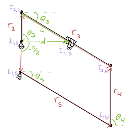
Once the basic topology was selected, I shifted to analytical synthesis. I created a parametric model of the linkage in MATLAB using vector loop equations to trace the coupler point’s path. My initial plan was to use dynamic equations to calculate the input torque required for constant crank acceleration, but after encountering unphysical results, I opted for a simpler and more intuitive approach. Knowing that the mechanical advantage is the inverse of the angular velocity ratio scaled by the ratio of link lengths, I swept the position of the fixed pin along the coupler link and plotted how the minimum mechanical advantage varied. I found an optimal configuration where the minimum mechanical advantage was 0.5 and the path aspect ratio was 2.5, which corresponded to a coupler length of 78.5 mm and a pin position one-third along the coupler.


Final Design


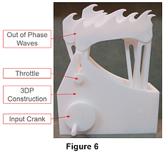
With the key dimensions defined, I finalized the design in SolidWorks and 3D printed the assembly. I incorporated an adjustable slider to control the amplitude of the horizontal motion and added spacers on the slider to prevent rubbing between the links and the crankshaft, which reduced joint lock-out. The resulting prototype runs smoothly and produces fluid, wave-like motion.